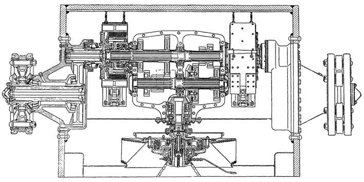
Plate 24 - Transmission of the tank
ENGINE CLUTCH
The engine clutch is multiplate, dry with steel friction plates. It consists of driving and driven parts and a withdrawal mechanism. The operation of the clutch from the driving compartment is carried out by means of a linkage (Plate 26).
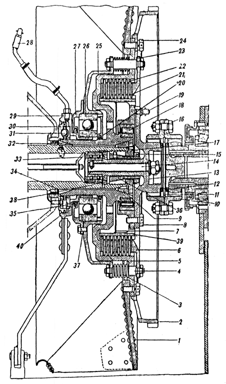
Plate 25 - Engine Clutch
| 1. Fan 2. Starter ring 3. Spring 4. Stud 5. Flywheel 6. Pressure plate 7. Oil excluder plate 8. Bolt 9. Cone 10. Coupling |
11. Ring 12. Packing 13. Hub 14. Scouring bolt 15. Nut 16. Fitted bolts 17. Plug 18. Roller bearing 19. Lubricator 20. Gland |
21. Driven plate 22. Driving plate 23. Lock washer 24. Bolt 25. Disengaging plate 26. Ball bearing 27. Cover 28. Lubricator 29. Control box 30. Fixed face cam |
31. Ball of withdraw mechanism 32. Cone 33. Ball bearing 34. Packing 35. Gland 36. Conical plug 37. Packing 38. Nut 39. Driven drum 40. Cast iron ring |
The driving plate of the clutch comprises of (Plate 25): flywheel (#5), disengaging plate (#25), pressure plate (#6) and ten steel driving plates (#22). The flywheel is seated on splines of the crankshaft, it is centered on it by two bronze cones (#9) and (#32) secured by a plug (#17) which is located by the cone (#36) tightened by the nut (#15) screwed on to its stem.
To safeguard against the cone moving and tightening the nut (#15), there is a dowel that fits into one of the slits of the plug (#17).
The internal surface of the flywheel is splined to mesh with the teeth of the driving plate (#22). Around the flywheel plate are positioned sixteen holes for the studs (#4). The fan (#1) is fitted to the flywheel plate on the side of the engine and on the side of the gearbox a toothed ring for the starter.
The fan is secured by 27 bolts, of which 24 are used to secure the toothed starter ring.
The disengaging plate (#25) and the pressure plate (#6) have sixteen holes. These plates (#25) and (#6) are joined to each other by the studs (#4) and are secured by nuts. The springs (#3) pressing against the friction plates are carried on the studs between the flywheel and disengaging plate. Between the shoulders of the studs (#4) and the pressure plate two washers (#13), 0.5 mm. are fitted. These washers are designed for the normal maintenance adjustment of the clutch.
The driving plates (#22) are made of steel; their outer circumferences are splined and are in mesh with the teeth of the flywheel. Thus all the driving components of the engine clutch rotate in one piece with the crankshaft.
The driven parts of the clutch comprise of: The driven drum (#39), with hub (#13) and twelve steel driven plates (#21).
The outer surface of the driven drum is splined and in mesh with the teeth of the driven plates. On the outside, the driven drum is connected to the hub, (the end of which is splined), by means of eight bolts.
The driven drum runs on a ball bearing (#18) seated on the hub of the flywheel. (In tanks of the first model the driven drum had two supports; a roller bearing on the hub of the flywheel and two ball bearings in the end of the crankshaft, through the tail piece of its hub, the driven drum rested on these bearings.
The connection between the driven drum and the driving shaft of the gearbox is in the form of a geared tooth coupling (#10). One half of the coupling meshes with the tooth of the hub (#13) and the other half with the gear of the driving shaft. Both: halves of the coupling are connected to one another by fitted bolts (#16).
The driven plates have teeth, the inside of which mesh with the toothed driven drum. All the driven plates of the engine clutch rotate in one piece with the driving shaft of the gearbox.
Withdrawal mechanism of the engine clutch comprises of:
The fixed face cam is bolted and doweled to the crankcase.
The control box is a press fit in the inner race of the ball bearing (#26) the outer race of which, is housed in a seating of the cover of the disengaging plate provided with felt ring oil seals. To the control box a grooved ring of special shape is fitted for balls. In the fixed face cam there are also grooves of the same shape on the other half of the face cam.
Between the fixed face cam and the control box there is a separator with balls which run in the grooves.
Note. In T-34 tanks with M-17 engine, the engine clutch is the BT type.
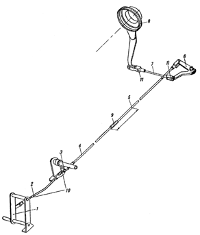
Plate 26 - Engine Clutch Control Linkage
| 1. Pedal 2. Inclined rod 3. Supporting lever 4. Front part of long tie-rod |
5. Rear part of long tie-rod 6. Double arm lever 7. Transverse lever |
8. Control box 9. Adjustment 10 & 11. Feed joints |
Adjustment of the clutch. A. To adjust the clearance in the balls of the withdrawal mechanism to within 0.9 -1.1 mm. 1. Unscrew the nuts securing the spring loaded studs (#4). 2. Remove the pressure plate. 3. Remove one adjusting washer from each stud. 4. Replace pressure plate.
If the travel of the tie-rod measures from 20 - 25 mm then the clearance in the balls of the withdrawal mechanism will be from 0.9 -1.1 mm.
B. To adjust the travel of the pressure plate to 6 to 7 mm. 1. Adjust the fork (#10) on the inclined tie-rod. 2. Alter the adjusting nut (#9) on the long tie-rod.
GEAR BOX
Translator's Note: The gearbox is of normal sliding mesh type of a very usual design with four speeds forward and one reverse and it has not been considered necessary to make a full translation of its description.
The gearbox casting is of aluminium and made in two halves. Recently it has been made of cast iron.
It is operated by a selector mechanism (Plate 30) on the right of the driver to which is fitted a lock to prevent reverse gear being accidentally engaged when moving forward.
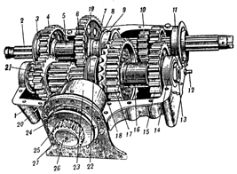
Plate 27 - General View Of The Gearbox (Without The Top Half Of Its Case)
| 1. Casing, lower half 2. Main shaft 3. Outer race of main shaft bearing 4. Fixed gear of 2nd speed 5. Spacer bush 6. Fixed gear of 1st speed . 7. Spacer bush |
8. Ring of cover of conical bearing 9. Cover of conical roller bearing of central support 10. Moving gear train for 3rd and 4th speed 11. Cover of roller bearing of outside support 12. Limiter of control box for disengaging steering clutch 13. Nut 14. Roller bearing of outside support |
15. Fixed gear of 3rd speed 16. Spacer bush 17. Fixed gear of 4th speed 18. Driven bevel gear 19. Cover of intermediate shaft 20. Intermediate shaft 21. Moving gear train for 1st and 2nd speeds |
22. Driving bevel gear 23. Cover of driving shaft 24. Gland nut 25. Geared coupling 26. Plug 27. Bracket |
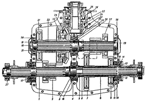
Plate 28 - Gearbox (Section Through Casing)
| 1. Main shaft 2. Gear train of 3rd and 4th speeds 3. Conical roller bearing 4. Cover of main shaft roller bearing 5. Nut 6. Spacer bush 7. Fixed (driven) gear of 1st speed 8. Spacer bush 9. Fixed gear of 2nd speed 10. Cover of outer supporting cylindrical roller bearing |
11. Roller bearing 12. Packing ring 13. Ring 14. Gland 15. Fixed face cam of steering clutch disengaging mechanism 16. Thrust ring 17. Bush 18. Intermediate shaft 19. Nut |
20. Roller bearing 21. Fixed gear of 3rd speed 22. Spacer bush 23. Fixed gear of 4th speed 24. Driven bevel gear 25. Cover of conical roller bearing of intermediate shaft 26. Conical roller bearing 27. 1st and 2nd speed gear train 28. Roller bearing |
29. Cover 30. Thrust ring 31. Adapter ring 32. Driven shaft 33. Cover rim 34. Roller bearing 35. driven roller bearing 36. Ball bearing 37. Spherical ball bearing |
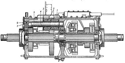
Plate 29 - Gearbox (Section Through Reverse Gear Train)
| 1. Reverse gear train 2. Roller bearing |
3. Ring nut 4. Floating washer |
5. Shaft of reverse gear train 6. Set screw |
7. Plate |
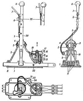
Plate 30 - Gear Selector
| 1. Base. of gear selector 2. Casing 3. Spherical nut 4. Protecting cover 5. Flexible cover 6. Cable 7. Locking handle |
8. Gear selector hand lever 9. Ball and socket joint 10. Plate spring 11. Horizontal selector rods 12. Locking ball 13. Locking plugs |
14. Locking catch 15. Looking spring 16. Rotating plate 17. Spindle of rotating plate 18. Return spring 19. Cover of locking gear |
20. Gear lever 21. Bolt 22. Check nut 23. Ball of look 24. Bracket 25. Retaining latch for reverse gear |
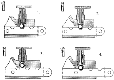
Plate 31 - Action Of Gear Selector Locking Device
|
|

Plate 32 - Action Of Gear Selector Lock
| 1. Neutral. 2. Central horizontal lever is moved. End levers are closed. 3. Right horizontal lever moved. Central and left levers are closed. |
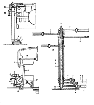
Plate 33 - Vertical Shafts
| 1. Tie-rod of 3rd and 4th gears 2. Tie-rod of reverse gear 3. Tie-rod of 1st and 2nd gears 4. Bottom lever of reverse gear 6. Bottom lever of 1st and 2nd gears 7. Shaft of 1st and 2nd gears |
8. Shaft of reverse gear 9. Shaft of 3rd and 4th gears 10. Top lever of 1st and 2nd gears 11. Top lever of reverse gear 12. Top lever of 3rd and 4th gears 13. Bracket 14. Lubricator |
15. Tie-rod for 1st and 2nd gears 16. Tie-rod for reverse 17. Tie-rod for 3rd and 4th gears 18. Cranked lover for 3rd and 4th gears 19. Tie-rod for 3rd and 4th gears 20. Ball 22. Pin |
STEERING CLUTCHES
The steering clutches are mounted on the main shaft of the gearbox. The internal driving drum (#3) (Plate 34) is splined on to the intermediate shaft of the gearbox, the external driven drum (#1) is fixed at the edges to the final drive. Between the internal and external drums there is a complete set of twenty-one driving and twenty-two driven plates each of which is geared to teeth of its corresponding drum.
The plates are compressed by springs (#19) acting through eighteen studs passing through openings of the plate of the internal, to the pressure plate (#2) seated on studs and fixed by nuts which are locked by flexible washers. The other extremity of the springs rest on the disengaging plate (#18) seated on the same studs and fixed by nuts. The withdrawal mechanism is operated by fixed face cams on the same principle as in the engine clutch (see drawings).
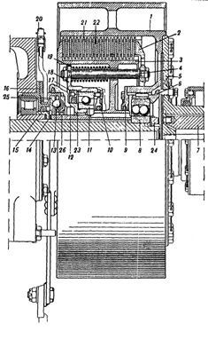
Plate 34 - Steering Clutch
| 1. External driven drum 2. Pressure plate 3. Internal driving drum 4. Stud 5. Steering clutch flange 6. Ring 7. driving shaft |
8. Two-point spherical ball bearing 9 & 10. Caps with glands 11. Ball bearing supporting radially 12. Control box 13. Withdrawal mechanism ball 14. Adjustment |
15. Ring 16. Fixed face cam 17. Stuffing box 18. Disengaging plate 19. Spring 20. Lubricator |
21. Driven plate 22. Driving plate 23. Washer 24. Nut 25. Fixed face cam ring 26. Control box ring |
BRAKES
The brakes which are used for parking, slowing down or steering are in the
form of "floating" bands which wrap round the outside of the driven end of the steering clutches. The steel bands are lined with Ferodo. In later models the internal surface of the brake bands have riveted cast iron linings.
The upper ends of the brake bands terminate in an adjusting bolt which is joined to a lug in the control lever and scoured by a pin.
The clearance between the brake band and the drum when the brakes are released should be maintained at 1.5 to 2.0 mm.
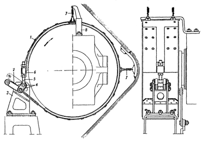
Plate 35 - Brake Band
| 1. Brake band 2. Actuating lever |
3. Bracket 4. Pins |
5. Adjusting bolt 6. Barrel Nut |
7. Spring 8. Securing arm |
CONTROL LINKAGE FOR STEERING CLUTCHES AND BRAKES
The control linkage for steering clutches and brakes (Plate 36), consists of the following main parts: steering levers (#1) with compensating device compensating shafts (#2) transfer shafts (#3) tie rods
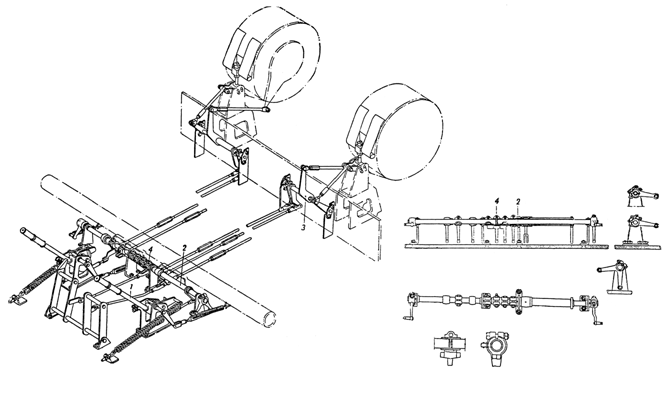
Plate 36 - Layout Of The Steering Clutch And Brake Controls
| 1. Steering lever with compensating mechanism |
2. Compensating shaft |
3. Transfer shaft |
4. Foot bake control |
The steering lever (#1) pivots on a shaft fixed in a bracket. This actuates a small lever (#4), of the foot brake linkage. This small lever is joined to the brake band through other levers connecting to the compensating shaft, tie-rods and levers of the transfer shaft.
The steering levers terminate in hooked levers, the internal working surfaces or which are ramped and bear against rollers fixed to a forked lever which is pivoted in the bracket. (Plate 37) One end of the forked levers is connected to a return spring and the other end to the control rod of the steering clutch. This tie-rod is connected through the compensating shaft, long tie-rod, transfer shaft and control lever to the control box of the steering clutch.
The connections between the separate components of the control linkage are shown in Plate 36.
The foot brake control consists of pedals, pedal tic-rods with two projections. One end of the pedal tie-rod is connected to the pedal and the other end to a small control lever (#4) which moves freely at the end of the two compensating shafts.
Action of the steering Control
When the steering lever is in the
extreme forward position, the force of the compensating springs is transferred
through the rollers to the bracket. On pulling the steering lever backwards the
spring pulls the forked lever forwards and disengages the steering clutch. When
the roller reaches the end of the ramp of the hook the disengagement of the
clutch is completed and the force of the clutch spring is transferred to the
bracket. All the force exerted by the driver is now used to operate the brake. A
fixing device is provided to hold the brakes on.
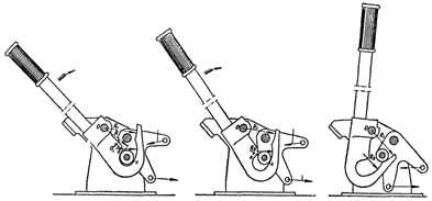
Plate 37 - Action Of The Steering Lever
| A. Force of unloader spring. B. Force of steering clutch spring. |
The fixing device (Plate 33) consists of the following parts : bracket (#5), toothed segment (#6), control lead (#7) and return spring (#8).
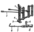
Plate 38 - Pedals Of Foot Brake And Engine Clutch With Fixing Device
| 1. Foot brake pedal 2. Tie-rod |
3. Bracket 4. Shaft |
5. Bracket 6. Toothed segment |
7. Control lead 8. Spring |
Adjustment to the Steering Clutches and Brakes and their Control Linkages 1. The clearance between the balls and the fixed face cam of the withdrawal mechanism of the steering clutch should be between 0.9 and 1.1 mm. 2. The travel (in one direction) of the long tie-rod of the steering clutches should be between the limits of 9 to 12 mm. 3. The clearance between the brake band and the drum should be within the limits of 1.5 to 2 mm. 4. The tie-rod should have 15 to 20 mm. horizontal travel before the brakes are applied.
FINAL DRIVE
The final drive (Plate 39) is mounted in casing (#16) incorporated into the tail of the tank and the hull side plates. The cover (#8) is attached to the casing by bolts. The final drive is a single hub reduction gear which transmits the torque to the sprocket wheel.
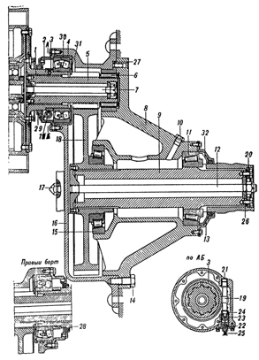
Plate 39 - Final Drive
| 1. Flange 2. Cover 3. Worm 4. Spherical roller bearing 5. Driving shaft with gear 6. Roller bearing 7. Assembly locking spindle 8. Cap of casing |
9. Driven shaft 10. Filler plug 11. Conical roller bearing 12. Assembly locking spindle 13. Cap 14. Bolt 15. Conical roller bearing 16. Casing |
17. Plug of lubricating aperture 18. Driven gear 19. Worm wheel shaft 20. Washer 21. Bush 22. Flanged bush 23. Internal bush 24. Sealing washer |
25. Speedometer cable casing 26. Washer 27. Cover of roller bearing 28. Sealing ring 29. Gland 30. Cover of spherical roller bearing 31. Sealing ring 32. Pressure ring of gland |
Maintenance of the Final Drive
1. After 500 km. disconnect the
tracks, remove the cap of the sprocket wheel and test the assembly locking
spindles (#2) for looseness. If necessary tighten up the nuts and slacken off
1/16 of a turn and re-fit with split pin.
2. After 1000 km. 1 kg of lubricant should be inserted through the opening in the cover of the casing and 2.5 kg into the greasing aperture. The lubricant should be 70% "Avia" oil and 30% "Konstalin".
| Back to the Main Page | Disclaimer |